 |
|
||||||||||||||||||||||||||||||||||||||||||||||||||
|
|||||||||||||||||||||||||||||||||||||||||||||||||||
|
|
||||||||||||||||||||||||||||||||||||||||||||||||||
|
|||||||||||||||||||||||||||||||||||||||||||||||||||
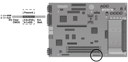
| Setting Power-On Password Jumpers
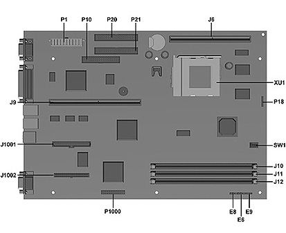
The Power-On Password feature is enabled or disabled by moving the plug on the E6 jumper located on the system board. The E6 jumper has three pins. The Power-On Password comes enabled by default with the plugs on pins 5 and 6. To clear or disable the Power-On Password, move the plug to pins 6 and 7. NOTE: To set a new password, move the E6 jumper back to pins 5 and 6, restart the computer, and reestablish your password through Security Management. |
| Clearing Configuration (CMOS)
To clear and reset the configuration perform the following procedure:
|
| Changing the Real-Time Clock (RTC) Battery
When installing the replacement RTC Battery, the battery connector is keyed and should be connected to the pins on the E9 battery header connector. |
 |
|
||||||||||||||||||||||||||||||||
|
|||||||||||||||||||||||||||||||||
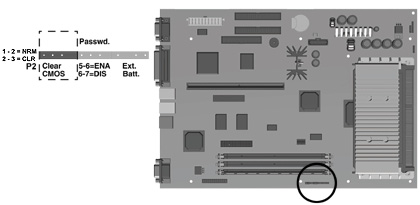
| Setting Power-On Password Jumpers
The Power-On Password feature is enabled or disabled by moving the plug on the E6 jumper located on the system board. The E6 jumper has three pins. The Power-On Password comes enabled by default with the plugs on pins 5 and 6. To clear or disable the Power-On Password, move the plug to pins 6 and 7. NOTE: To set a new password, move the E6 jumper back to pins 5 and 6, restart the computer, and reestablish your password through Security Management. |
| Clearing Configuration (CMOS)
To clear and reset the configuration perform the following procedure:
|
| Changing the Real-Time Clock (RTC) Battery
When installing the replacement RTC Battery, the battery connector is keyed and should be connected to the pins on the E9 battery header connector. |
 |
|
||||||||||||||||||||||||||||||||||||||||
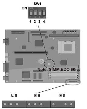
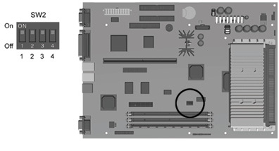
| Switch Settings: The following table identifies the switch settings for each processor frequency for the Pentium-based system boards. | ||||||||||||||||||||||||||||||
|
||||||||||||||||||||||||||||||
| Possible Bus Speed Settings | ||||||||||||||||||||||||||||||
|
||||||||||||||||||||||||||||||
| System Board Jumpers
This section provides information for setting jumpers for enabling/disabling passwords and clearing the configuration (CMOS). When you change a security feature, you will need to reset a jumper and reconfigure the computer to recognize this change. If the system configuration is incorrect, your computer may not work properly and you may receive error messages on the screen. Setting the system board jumpers is part of the reconfiguration process, along with running the Computer Setup utility.
|
||||||||||||||||||||||||||||||
| Setting Power-On Password Jumpers
The power-on password feature is enabled or disabled by moving the plug on the E6 jumper located on the system board. The E6 jumper has three pins. The power-on password comes enabled by default with the plug on pins 5 and 6. To clear or disable the power-on password, move the plug to pins 6 and 7. To set a new password, move the E6 jumper back to pins 5 and 6, restart the computer, and reestablish your password through Security Management. |
||||||||||||||||||||||||||||||
| Clearing Configuration
The computer's configuration (CMOS) may occasionally be corrupted. If it does, it is necessary to clear the CMOS memory. To clear and reset the configuration, perform the following procedure:
|
||||||||||||||||||||||||||||||
| Changing the Real-Time Clock (RTC) Battery
When installing the replacement RTC Battery, the battery connector should be connected to the pins on the E9 battery header connector. The battery connector is keyed for proper installation. |
||||||||||||||||||||||||||||||
 |
|
||||||||||||||||||||||||||||||||||||
 |
|
||||||||||||||||||||||||||||||
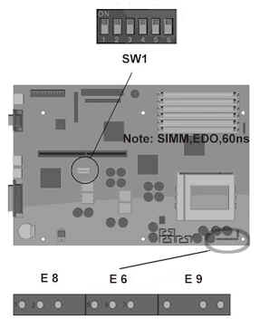
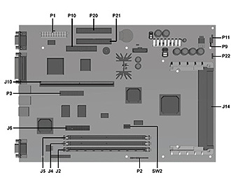
| System Board Jumpers
This section provides information for setting jumpers for enabling/disabling passwords and clearing the configuration (CMOS). When you change a security feature, you will need to reset a jumper and reconfigure the computer to recognize this change. If the system configuration is incorrect, your computer may not work properly and you may receive error messages on the screen. Setting the system board jumpers is part of the reconfiguration process, along with running the Computer Setup utility. |
|||||||||||||||||||||||||||||||
| Setting Power-On Password Jumpers
The power-on password feature is enabled or disabled by moving the jumper on the password header located on the system board. The password header is labeled "Password" on the Pentium II system board.The password header has three pins. The power-on password comes enabled by default with the jumper on pins 5 and 6. To clear or disable the power-on password, move the jumper to pins 6 and 7. |
|||||||||||||||||||||||||||||||
| Password Header Location, Pentium II System
Board
|
|||||||||||||||||||||||||||||||
| To set a new password, move the password header back to pins 5 and 6, restart the computer, and reestablish your password through Security Management. | |||||||||||||||||||||||||||||||
| Clearing Configuration
The computer's configuration memory (CMOS) may occasionally be corrupted by static electricity. This happens very rarely. When it does occur, it is usually due to software or hardware that is not executing accurately or by adding or removing expansion boards to or from the computer. If the computer's configuration memory becomes corrupted, it is necessary to clear the configuration memory. To clear and reset the configuration memory: Be sure the computer is powered off before beginning this procedure. 1. Locate the appropriate jumper. For Pentium systems, this jumper is labeled E8. For Pentium II systems, it is labeled P2. 2. Remove the plug from pins 1 and 2, place it on pins 2 and 3, then return it to pins 1 and 2. Locating the E8 Jumper on the Pentium System Board Locating the P2 Jumper (Pins 1-3) on the Pentium II System Board |
|||||||||||||||||||||||||||||||
| Clear CMOS Header Location, Pentium II System
Board
3. Replace the cover and tighten the thumbscrews on the rear panel. 4. Turn the computer on. 5. Run the Computer Setup utility to reconfigure the system. |
|||||||||||||||||||||||||||||||
| When jumper on the clear-CMOS header is removed, the password becomes invalid because the password is stored in the configuration memory. You will need to reset the password. | |||||||||||||||||||||||||||||||
| Changing the Real-Time Clock (RTC) Battery
When installing the replacement RTC battery, the battery connector should be connected to the pins of the battery connector on the system board. The battery connector is labeled "Ext. Batt." on the Pentium II system board. The battery connector is keyed for proper installation. |
|||||||||||||||||||||||||||||||
|
|
|
 |
 |
|
|
|
|
|
|